Electrical control panels are so complex that there are various kinds of questions about their basics that we get every day, including what type of equipment we use, how the panels are wired, how to keep the panel and cabinet within a normal temperature range, and so on.
to see what the basic components of a control panel are, how they are wired, the function of a thermostat and so on, we proceed on this article to know more.
We will be discussing a control panel for a system that converts wastewater into clean water.
Using this control panel, wastewater is cleaned and turned into drinking water.
Control Panel Size
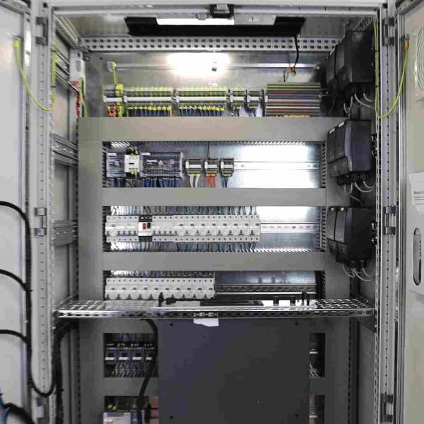
We are going to review a 2-door control panel.
control panels based on the number of doors they have are named differently.
Control panel enclosures come in one-, two-, and three-door designs, depending on how big your panels are. The more devices you have, the larger the control cabinet will have to be.
Switches on the Panel Door
A couple of switches are attached to the PLC inputs and outputs on the front of the panel.
Mute Buzzer
This is the button that you use since there is an active alarm on the system.
When there is an active alarm on the system whoever is responsible on the factory floor, presses this button to acknowledge the alarm and mute the buzzer.
Muting the buzzer means the alarm is still there and still visible on the HMI (Human Machine Interface), but the buzzer has stopped sounding.
when alarm is active on the system, and it’s making that crazy loud noise, the engineer or technician may press this button to mute the buzzer, and by doing so, they acknowledge of being aware of the alarm as well.
Accordingly, next time that you see an alarm on the HMI, but there is no sound, apparently means that somebody has already acknowledged the alarm.
Next we have we have the Emergency Shutdown push button or the E-Stop as it might be called.
As the name designates, you use this switch to shut down the whole system when there is an emergency, and by doing so you can avoid damage being caused to the system, or the people around.
We protect this button with a cover to prevent unintentional use by people and if if someone presses this button unintentionally the whole system will be shut down completely. a red alarm indicator appears on the HMI screen when you press the Emergency-Stop switch.
After the emergency is solved and you desire to run the system again, you may press the ESD Reset button, or Emergency Shut down Reset, to remove the alarm and the indicator on the HMI.
Lock mode of Emergency switch
When The Emergency-Stop is pressed goes to the lock mode.
In order to unlock the switch and turn it back to the normal mode we can twist it, and the switch will get back to the normal mode again.
How the switches on the panel door are connected to the PLC
It is visible on the back of the door the switch is wired all the way to the PLC input.
Control panel components
a breakdown of all components supporting this panel and their connections.
CPU
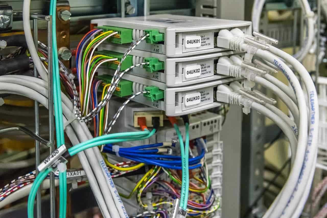
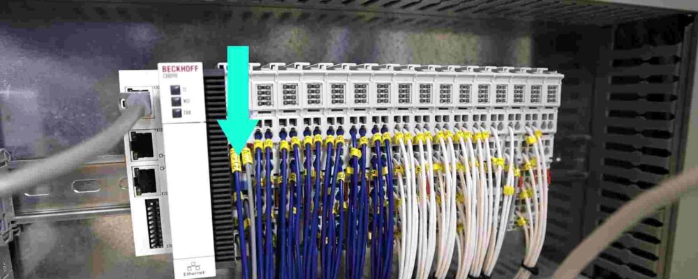
Our first module, a CPU, works as the brain of the PLC. It has a few LEDs, Ethernet, and various DIP switches.
Input and output cards
Next, we have the input and output cards.
Of these cards, those with blue wires are digital input, and output cards and those with the white wires are analog input and output cards.
So you see that we apply separate cards for digital and analog signals.
PLC shown above is a unit that includes a CPU and a few input and output cards, which together make up the PLC hardware.
PLC wiring
Have a look at the wires that are connected to the PLC.
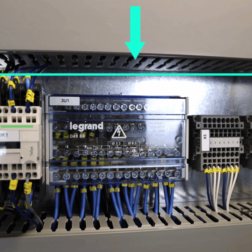
These wires come all the way through the trunking, and then they are connected to the terminals inside the pannel.
one end of the wires is connected to the PLC cards, and the other end is connected to the terminals.
Gland plate
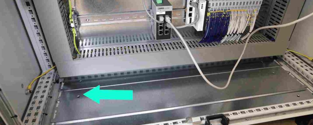
First, we make some holes on the bottom of this panel, like the holes that we have in the image below.
This is called a gland plate and allows the cables to come into the panel. Then, we put them into the trunking and connect them to the other end of the terminals.
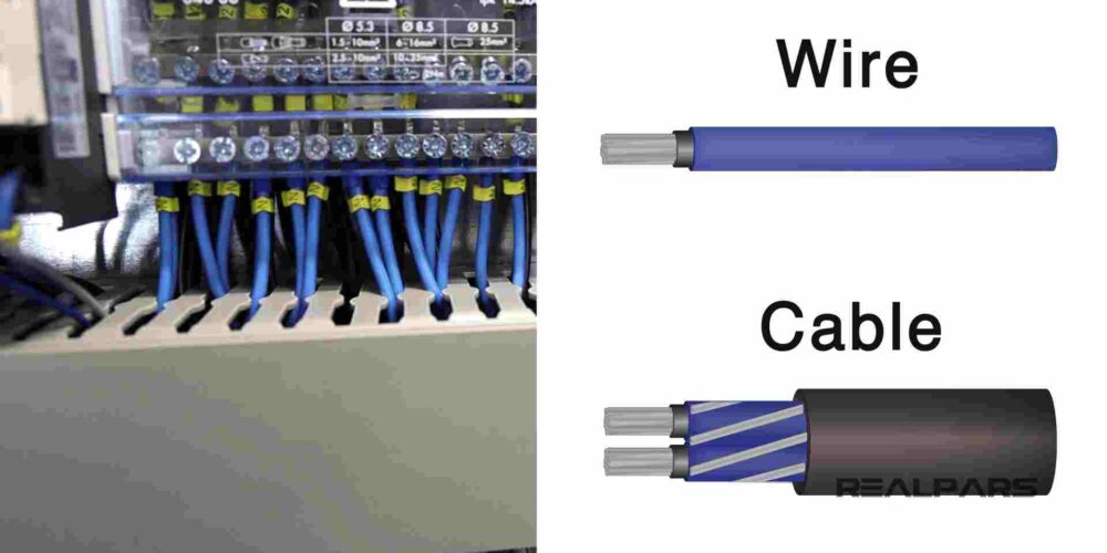
Kindly note that we are using the term cable here instead of wire. What is the difference?
The wire is a single conductor, but a cable is a group of wires that are covered in a jacket.
Outside of the control panel, you use cables, but inside the panel, you remove the jacket and use the wires Because inside the panel, you need to label every single wire. And now it comes a question that why labeling? You need to label each wire to be able to make them identifiable, which helps with troubleshooting if there is an issue.
It is much better to label the wire at both ends, so you know exactly where each end terminates.
Ethernet switch
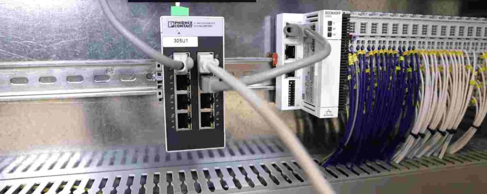
As you can see in the image below, the PLC is connected to an Ethernet switch via a cable.
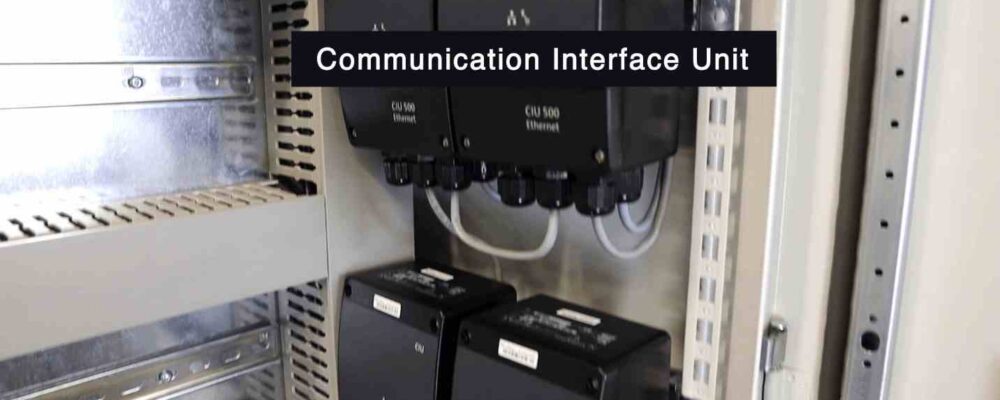
From the other end, the Ethernet switch is connected to other devices which we call them Communication Interface Unit or CIU.
It is good to add the PLC is connected to the Ethernet switch first, then the switch is connected to the Interface Units, and later the other end of the units are connected to other devices.
Some field devices are connected to the PLC directly via wires, and some others are connected via Ethernet cables.
Power supplies control panel
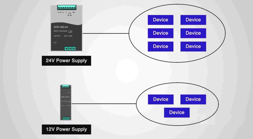
in the control panel there are a couple power supplies. The bigger one in our panel has 24-Volt DC output voltage and 20A (or sometimes shortened to Amp or Amps) output current.
The small one has 12 Volt DC output voltage and 10A output current.
Both of these power supplies receive 220 Volt AC as input.
The bigger one and the smaller one give you 24 Volt DC in the output, and 12 Volt DC on the output, respectively.
It may be a question for you that why we have two power supplies? because we have some devices in the control panel that works with 24 Volt DC and some other devices that work with 12 Volt DC.
It might be interesting for you to know why the 24 Volt power supply has a greater output amperage compared to the 12 Volt power supply?
This is because the number of devices, or the devices themselves, powered by the 24 Volt power supply require more input current to operate than those powered by the 12 Volt power supply.
How do we size PLC power supplies?
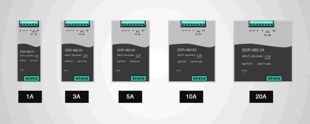
We usually size the power supplies based on the amount of current output that we need.
For example, we have power supplies with 1 Amp, 3 Amp, 5 Amp, 10 Amp, and 20 Amp output current.
The more devices we have, the more current we need and the bigger the power supply gets.
